Cat5 connections
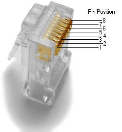
The RJ45 plug is an 8-position modular connector that looks like a large phone plug. There are a couple variations available. The primary variation is whether the connector is intended for stranded or solid wire. For stranded/braided wires, the connector has sharp pointed contacts that actually pierce the wire. For solid wires, the connector has fingers which cut through the insulation and make contact with the wire by grasping it from both sides. The connector is the weak point in an ethernet cable, choosing the wrong one will often cause problems later.
RJ45 jacks come in a variety styles intended for different mounting options. The choice is one of requirements and preference. RJ45 jacks are designed to work only with solid cable. Most jacks come labeled with color codes for either T568A, T568B or both. Make sure you choose the correct one.
RJ45 Plug and Jack Pin Out - Ethernet Cable Pin Outs:
There are two basic cable pin outs. A straight through cable, which is used to connect to a hub or switch, and a cross over cable used to operate in a peer-to-peer fashion without a hub/switch. Generally all fixed wiring should be run as straight through. Some ethernet interfaces can cross and un-cross a cable automatically as needed, a handy feature.
Standard, Straight-Through Wiring (both ends are the same):
| T568A | Straight Through | |||
| Pin | Colour | |||
| 1 | White/Green | |||
| 2 | Green | |||
| 3 | White/Orange | |||
| 4 | Blue | Unused | ||
| 5 | White/Blue | Unused | ||
| 6 | Orange | |||
| 7 | White/Brown | Unused | ||
| 8 | Brown | Unused |
| T568B | Cross-over | |||
| 1 | White/Orange | |||
| 2 | Orange | |||
| 3 | White/Green | |||
| 4 | Blue | Unused | ||
| 5 | White/Blue | Unused | ||
| 6 | Green | |||
| 7 | White/Brown | Unused | ||
| 8 | Brown | Unused |
+Note: The cross over cable layout is suitable for 1000Base-T operation, all 4 pairs are crossed.
Wiring Ethernet Cables:
Strip off about 2 inches of the cable sheath. Untwist the pairs - don't untwist them beyond what you have exposed, the more untwisted cable you have the worse the problems you can run into.
Align the colored wires according to the diagrams above.
Trim all the wires to the same length, about 1/2" to 3/4" left exposed from the sheath.
Insert the wires into the RJ45 plug - make sure each wire is fully inserted to the front of the RJ45 plug and in the correct order. The sheath of the cable should extend into the RJ45 plug by about 1/2" and will be held in place by the crimp.
Crimp the RJ45 plug with the crimper tool.
Verify the wires ended up the right order and that the wires extend to the front of the RJ45 plug and make good contact with the metal contacts in the RJ45 plug
Cut the cable to length - make sure it is more than long enough for your needs.
Repeat the above steps for the second RJ45 plug.
How to wire fixed Ethernet Cables:
Run the full length of cable in place, from endpoint to endpoint, making sure to leave excess.
At one end, cut the wire to length leaving enough length to work, but not too much excess.
Strip off about 2 inches of the cable sheath.
Align each of the colored wires according to the layout of the jack.
Use the punch down tool to insert each wire into the jack.
Repeat the above steps for the second RJ45 jack.
If a cable tester is available, use it to verify the proper connectivity of the cable. If your cable doesn't test out correctly look closely at each end and see if you can find the problem. Often a wire ends up in the wrong place or one of the wires is making no contact or poor contact. Also double check the color coding to verify it is correct. If you see a mistake or problem, cut the end off and start again. A cable tester is invaluable at identifying and highlighting these issues.
When determining the length of cables remember that an end to end connection should not extend more than 90m. Minimize the cable length, the longer the cable the more performance deteriorates. This is noticeable as a gradual decrease in speed and increase in latency.
See also Cat5 Connector types
