Glossary AV terms
Glossary of Audio Visual Terms - A useful selection of common technical terms used in an audio visual context
AWG American Wire Gauge
American wire gauge (AWG), also known as the Brown & Sharpe wire gauge, is a standardized wire gauge system used since 1857 predominantly in the United States for the diameters of round, solid, nonferrous, electrically conducting wire. The cross-sectional area of each gauge is an important factor for determining its current-carrying capacity. Often seen in standards and specifications for audio and video cables. See also ... AWG and metric wire sizes and electrical parameters
Balanced and Unbalanced Audio (and microphones)
Unbalanced Audio Most domestic audio equipment has unbalanced audio inputs and outputs. This means that the audio output (left, right, or mono) appears on a single wire, and the other wire is connected to earth (Ground). Typical connectors used are RCA "phono" connectors, DIN plugs/sockets, and 6.3mm or 3.5mm jack plugs/sockets.
Unbalanced audio is fine for the domestic environment, and for line-level signals in a typical broadcast studio. Problems start to occur if the signals are being carried over long distances, where interference affects the signal wire and especially if the source and destination have separate mains supplies.
Balanced Audio
A lot of professional equipment will have balanced audio inputs and outputs, usually on 3-pin "XLR" connectors. A balanced audio signal consists of a pair of wires carrying the audio signal with a separate earth wire or screen.When one signal wire carries a positive voltage, the other carries an equal and opposite negative voltage.
The 3 wires used in a typical XLR lead are often referred to as Ground, Live and Return, or Ground, Hot and Cold. "Live" and "Return" carry the "positive" and "negative" elements of the signal respectively. Calling the signals "Live" and "Return" makes it nice and easy to remember which goes on which pin of the XLR plug/socket:
X = Ground L = Live R = Return
The advantage of balanced audio over unbalanced audio is it's ability to reject external interference. The receiving equipment takes the voltage difference between the two wires as the input signal. Interference will usually get added to both wires equally, and so gets ignored by the receiving equipment.
Recording and broadcast studios commonly use phantom powering as a means to provide power to microphones. Power may be needed either for a device that requires power such as a pre-amp on an electret microphone or because the mic is a type that intrinsically requires powering such as a condenser microphone. Since the microphone has only one pair of wires the return path for the power has to be provided elswhere. This is usually done via the "phantom" circuit (the centre point of a transformer winding) and the microphone cable screen (ground).
"All you need to know about microphones" is a useful but a little lengthy article summarising microphone types and their uses.
Cat 5 Cable
Category 5 cable, is a twisted pair (4 pairs) high signal integrity cable type often referred to as "Cat5". Many such cables are unshielded (UTP) but some are shielded (STP). Category 5 has been superseded by the Category 5e specification structured cabling for computer networks such as Ethernet, and is also used to carry many other signals such as basic voice services, token ring, and ATM (at up to 155 Mbit/s, over short distances). Equipment is available for transmitting VGA and other audio video signals over Cat 5 cable.
See also : Cat5 Pinouts and connections and Cat5 Connector types
CE mark
The CE marking (also known as CE mark) is a mandatory conformity mark on many products sold in the European Economic Area (EEA). The CE marking certifies that a product has met EU consumer safety, health or environmental requirements.
The CE marking (an acronym for the French "Conformite Europeenne") certifies that a product has met EU health, safety, and environmental requirements, which ensure consumer safety. Manufacturers in the European Union (EU) and abroad must meet CE marking requirements where applicable in order to market their products in Europe.
Unfortunately, there is no comprehensive list of the products that require a CE marking. Therefore, it is the manufacturer's responsibility to determine if a product requires a CE marking.
To permit the use of a CE mark on a product, proof that the item meets the relevant requirements must be documented. Sometimes this is achieved using an external test house which evaluates the product and its documentation. Often it is achieved by a company-internal self-certification process. In any case the responsible organization (manufacturer, representative, importer) has to issue a EC-Declaration of Conformity (EC-DoC) indicating its identity (location, etc.), the list of European Directives it is declaring compliance with, a list of standards the product complies with, and a legally binding signature on behalf of the organization. The EC-DoC underlines the sole responsibility of the manufacturer.
Some examples for which manufacturers can self-certify (which apply to AV products) include:
- Electromagnetic Compatibility (EMC) Directive
- Low Voltage Directive(LVD)
- Most products covered by the Radio and Telecommunications Terminal Equipment (R&TTE) Directive
CD: Compact Disc
Compact Disc. Ubiquitous digital audio format. Uses 16-bit/44.1-kHz sampling rate PCM digital signal to encode roughly 74 or 80 minutes of two-channel, full-range audio onto a 5-inch disc.
CD-R
Recordable Compact Disc
CD-RW
Rewritable Compact Disc
Component Video
Component video signal
A signal that's recorded or transmitted in its separate components. Typically refers to Y/Pb/Pr, which consists of three 75-ohm channels: one for luminance information, and two for color. Compared with an S-video signal, a Y/Pb/Pr signal carries more color detail. HDTV, DVD, and DBS are component video sources, though most DBS material is transcoded to component from composite signals
Component Video Component Video is a method of delivering quality video (RGB) in a format that contains all the components of the original image. These components are referred to as luma and chroma and are defined as Y'Pb'Pr' for analogue component and Y'Cb'Cr' for digital component.
Component video is available on some DVD players and projectors and normally uses 3 separate RCA connectors.
Composite Video
The combined picture signal, including vertical and horizontal blanking and synchronizing signals transmitted in a single cable which is often fitted with a yellow RCA connector.
Connectors
Banana Plug
A banana connector (commonly banana plug for the male, banana jack for the female) is a single-wire (one conductor) electrical connector used for joining wires to equipment. The plugs are frequently used to terminate patch cords for electronic test equipment. They are also used as the plugs on the cables connecting the amplifier to the loudspeakers in a hi-fi sound system.
DVI connector
The Digital Visual Interface (DVI) is a video interface standard designed to maximize the visual quality of digital display devices such as flat panel LCD computer displays and digital projectors. DVI was developed by the Digital Display Working Group (DDWG). This interface provides a high-speed connection for visual data that is display technology independent. DVI interface primarily focused at providing a connection between computer and display device.
See Also: DVI connections
HDMI connector
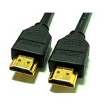
HDMI - High-Definition Multimedia Interface. HDMI was developed by Hitachi, Matsushita, Royal Philips, Silicon Image, Sony, Thomson and Toshiba. There are three different connector types: Type A for single-link connection, Type B for dual-link (very high resolutions) connection, and Type C for video cameras, etc.
See also : HDMI connections
Phono connector
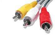
An RCA jack, also referred to as a phono connector or Cinch connector, is a type of electrical connector that is commonly used in the audio/video market. The name "RCA" derives from the Radio Corporation of America, which introduced the design by the early 1940s to allow mono phonograph players to be connected to amplifiers.
RCA Connectors (CINCH/AV)
A connector designed for coaxial cables, though often used on twin audio cable too, carrying line-level audio signals or speaker connections. An RCA jack, also called a phono connector or CINCH/AV connector, is a type of electrical connector that is commonly used in the audio/video market. The name "RCA" derives from the Radio Corporation of America , which introduced the design by the early 1940s to allow phonograph players to be connected to amplifiers. For many other applications it began to replace the older jack plugs used in the audio world when component high fidelity started becoming popular in the 1950s. The corresponding plug is called an RCA plug or a phono plug, as opposed to a phone plug.
RCA connections includes RCA to mini-jack connections
RJ11 : Registered Jack-11
A telephone connector that holds up to four wires. The RJ-11 is the common connector used to plug a telephone handset into the telephone and in some cases the telephone into the wall (in UK a BT connector is used) . A six-wire variation of RJ-11 is also used.
RJ45 : Registered Jack - 45
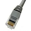
Eight wire RJ45 connectors used with Ethernet and Token ring type networks. The common form of Datacomms connector used in office wiring systems often called Cat 5 connector.
TRS - Tip Ring Sleeve (Audio Jack, 3.5mm Mini Jack 6.3mm Jack)
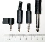
A TRS connector (tip, ring, sleeve) also called an audio jack, phone plug, jack plug, stereo plug, mini-jack, or mini-stereo, is a common audio connector. It is cylindrical in shape, typically with three contacts, although sometimes with two (a TS connector) or four (a TRRS connector). It was invented for use in telephone switchboards in the 19th century and is still widely used, both in its original 1/4" (6.3 mm) size and in miniaturized versions 1/8" (3.5 mm) and 3/32" (2.5 mm). The connector's name is an initialism derived from the names of three conducting parts of the plug: Tip, Ring, and Sleeve – hence, TRS.
In the UK, the terms jack plug and jack socket are commonly used for the respectively male and female TRS connectors
Speakon Connector
The Speakon is an audio cable connector, originally manufactured by Neutrik, mostly used in professional audio systems for connecting loudspeakers to amplifiers. The same manufacturer produces another connector dubbed PowerCon, which is designed to carry mains power rather than audio signal. The audio and power designs cannot connect to each other.
A Speakon connector is designed with a locking system that may be designed for soldered or screw-type connections. Line connectors (female) mate with (male) panel connectors and typically a cable will have identical connectors at both ends. If it is needed to join cables, a coupler can be used (which essentially consists of two panel connectors mounted on the ends of a plastic tube). Speakon connectors are a higher current carrying alternative to TS connectors (1/4-inch phone jacks), two-pole twist lock, and XLR connectors for loudspeakers. Speakon connectors lock into their sockets with a twisting motion, making them significantly less prone to disconnection than standard TRS plugs.
Speakon connectors are fully shielded from human touch, preventing electrical shock risks associated with high power audio amplifiers and unshielded connections. Speakon contacts do not short out upon connection or disconnection, which can happen to the 1/4-inch plug as it is being plugged in. This can be a benefit when working with sound equipment that is in operation. Speakon connectors are designed to be unambiguous in their use in speaker cables. With jack and XLR connections, it is possible to use low-current shielded microphone or instrument cables in a high-current speaker application. Speakon cables are intended solely for use in high current audio applications.
Speakon connectors are made in two, four and eight-pole configurations. The two-pole line connector will mate with the four-pole panel connector, connecting to +1 and −1; but the reverse combination will not work. The eight-pole connector is physically larger to accommodate the extra poles. The four-pole connector is the most common at least from the availability of ready-made leads, as it allows for things like Bi-amping (two of the four connections for the higher-frequency signal, with the other two for the lower-frequency signal) without two separate cables. Similarly, the eight-pole connector could be used for Tri-amping (two poles each for low, mid and high frequencies with two unused), or quad-amping (two poles each for high, mid, low and sub).
Another use for the four-pole cable is to carry two channels of amplified signal from an amplifier to a pair of loudspeakers using a 'combiner' Y-lead connected to the two output channels, and a 'splitter' Y-lead to feed the loudspeakers. Essentially the 'combiner' and 'splitter' Y-leads are the same - three four pole line connectors with a 2-core cable between +1 and -1 on two connectors, and the remaining +2 and -2 on one connecter to +1 and -1 on the third. Some amplifiers and mixer-amplifiers are configured to do this without the need for a 'combiner'.
S-Video Connector
S-Video is commonly used in many consumer TVs, DVD players, video tape recorders, game consoles and almost all TV-out connectors of graphics cards.
VGA connector
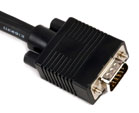
A VGA connector as it is commonly known (other names include RGB connector, D-sub 15, mini sub D15 and mini D15) is a three-row 15 pin DE-15 connector (ie a D sub-miniature connector with E size case and 15 pins).
See Also : VGA Connections for pin-out details etc and this article VGA cables and connectors for Projectors and monitors which covers VGA cable and connector designs and how to avoid interference.
XLR connector
The XLR connector is an electrical connector design. XLR plugs and sockets are used mostly in professional audio and video electronics cabling applications where a "balanced" connection is used allowing long lengths of cable to be used without excessive interference. Home audio and video electronics normally use RCA connectors (not balanced).
USB
See below USB (Universal Serial Bus)
DDC - Display Data Channel
The Display Data Channel or DDC is a digital connection between a computer display (monitor or projector usually) and a graphics adapter that allows the display to communicate its specifications to the adapter and adjust parameters such as brightness and contrast from the computer host. The standard was created by the Video Electronics Standards Association (VESA). Extra wires can be included in VGA cables to enable DDC operation.
Decibel (dB)
The decibel (dB) is used to measure sound level, but it is also widely used in electronics, signals and communication. The dB is a logarithmic unit used to describe a ratio. The ratio may be power, sound pressure, voltage or intensity or several other things.
A whisper is about 20 dB. A normal conversation is typically from 60 to 70 dB, and a noisy factory from 90 to 100 dB. Loud thunder is approximately 110 dB, and 120 dB borders on the threshold of pain.
DI Unit
A DI unit, DI box, Direct Box or simply DI is an electronic device that connects a high impedance, line level, unbalanced output signal to a low impedance mic level balanced input, usually via XLR connector. DIs are frequently used to connect an electric guitar or electric bass to a mixing console's microphone input. The DI performs level matching, balancing, and either active buffering or passive impedance bridging to minimise noise, distortion, and ground loops. DIs do not perform impedance matching.
Dolby
Dolby Digital
An encoding system that digitally compresses up to 5.1 discrete channels of audio (left front, center, right front, left surround, right surround, and Low Frequency Effect (LFE)) into a single bitstream, which can be recorded onto a DVD, HDTV broadcast, or other form of digital media. When RF-modulated, it was included on some laser discs, which requires an RF-demodulator before the signal can be decoded. Five channels are full-range; the .1 channel is a band-limited LFE track. A Dolby Digital processor (found in most new receivers, preamps, and some DVD players) can decode this signal back into the 5.1 separate channels. Most films since 1992's Batman Returns have been recorded in a 5.1 digital format, though a number of films before that had 6-channel analog tracks that have been remastered into 5.1.
Dolby EX
An enhancement to Dolby Digital that adds a surround back channel to 5.1 soundtracks. The sixth channel is matrixed from the left and right surround channels. Often referred to as 6.1. Sometimes referred to as 7.1 if the system uses two surround back speakers, even though both speakers reproduce the same signal. Software is backwards-compatible with 5.1 systems, but requires an EX or 6.1 processor to obtain additional benefit.
Dolby Pro Logic
An enhancement of the Dolby Surround decoding process. Pro Logic decoders derive left, center, right, and a mono surround channel from two-channel Dolby Surround encoded material via matrix techniques.
Dolby Pro Logic II
An enhanced version of Pro Logic. Adds improved decoding for two-channel, non-encoded soundtracks and music.
DTS - Digital Theater Systems
A digital sound recording format, originally developed for theatrical film soundtracks, starting with JurassicPark. Records 5.1 discrete channels of audio onto laser discs, CDs, and DVDs. Requires a player with DTS output connected to a DTS processor. A competitor of Dolby Digital and it's drivatives
DVD - Digital Versatile Disc
DVD, also known as "Digital Versatile Disc" or "Digital Video Disc," is an optical disc storage media format. Its main uses are video and data storage. DVDs are of the same dimensions as compact discs (CDs) but store more than six times as much data.
Variations of the term DVD often describe the way data is stored on the discs: DVD-ROM (Read Only Memory), has data that can only be read and not written, DVD-R and DVD+R can record data only once and then function as a DVD-ROM. DVD-RW, DVD+RW and DVD-RAM can both record and erase data multiple times. The wavelength used by standard DVD lasers is 650 nm, and thus the light has a red color.
DVD-Video and DVD-Audio discs respectively refer to properly formatted and structured video and audio content. Other types of DVDs, including those with video content, may be referred to as DVD-Data discs.
As next generation High Definition more advanced optical formats such as Blu-ray Disc also use a disc identical in some aspects, the original DVD is occasionally given the retronym SD DVD (for standard definition).[2][3] However, the trademarked HD DVD discs have been discontinued since Blu-ray absorbed their market share.
DVI: Digital Visual Interface.
A connection standard developed by Intel for connecting computers to digital monitors such as flat panels and DLP projectors. A consumer electronics version, not necessarily compatible with the PC version, is used as a connection standard for HDTV tuners and displays. Transmits an uncompressed digital signal to the display. The latter version uses HDCP copy protection to prevent unauthorized copying. See also HDMI.
EIA - Electronics Industries Alliance
The Electronic Industries Alliance (EIA, until 1997 Electronic Industries Association) is a trade organization composed as an alliance of trade associations for electronics manufacturers in the United States. Those associations in turn govern sectors of EIA standards activity.
EMI - Electromagnetic Interference
Graphic Equalizer
A type of equalizer with sliding controls that create a pattern representing a graph of the frequency-response changes. Raising sliders boosts the affected frequencies; lowering sliders cuts (attenuates) the affected frequencies.
EMC - Electro Magnetic Compatibility
EMC stands for Electro Magnetic Compatibility, and describes the way electric or electronic apparatus behave (regarding Electro Magnetic aspects) in the presence of other equipment.
Electrical products (though not clearly specified which products) imported into the European Community must comply with the EMC directive.
The EMC Technical Committee of the IEEE in the USA is committee is concerned with the measurement and instrumentation requirements in EMC standards and procedures and how they are interpreted.
HDR: Hard-Drive Recorder.
A device that uses a computer hard drive to store compressed digital audio and video signals.
HDMI: High-Definition Multimedia Interface
HDMI is the current state-of-the-art in delivering the highest quality video and audio through a single cable. HDMI can send high definition video (HDTV) as well as surround sound. Most recent HDTV television and mid- to upper-end home theatre receivers and DVD players offer HDMI connections.
HDMI is also compatible with most DVI connections for video so if you have, say a DVD player with DVI output and a plasma TV with HDMI input, you can use an HDMI-to-DVI cable to connect them, although you will need a separate connection for the audio, such as optical digital or coaxial digital. See article in "Tips and Articles"
HDTV: High Definition Television
The high-resolution subset of our DTV system. The FCC has no official definition for HDTV. The ATSC defines HDTV as a 16:9 image with twice the horizontal and vertical resolution of our existing system, accompanied by 5.1 channels of Dolby Digital audio. The CEA defines HDTV as an image with 720 progressive or 1080 interlaced active (top to bottom) scan lines. 1280:720p and 1920:1080i are typically accepted as high-definition scan rates.
Home Theatre in a Box
A complete home theatre system in one box (or at least sold together as a package). Consists of five or more speakers, a subwoofer, and a receiver. May also include a DVD player.
IEEE 1394: Firewire
A networking standard for PCs. Combined with 5C copy protection, is used as a two-way connection to transfer the MPEG-compressed digital bitstreams between consumer electronics items, including HDTV tuners and displays, D-VHS recorders, DVD players, and DBS receivers. Also called FireWire, iLink
Interlace:
Process of alternating scan lines to create a complete image. In CRT displays, every second field/frame is scanned between the first field/frame. The first field represents the odd lines; the second field represents the even lines. The fields are aligned and timed so that, with a still image, the human eye blurs the two fields together and sees them as one. Interlace scanning allows only half the lines to be transmitted and presented at any given moment. A 1080i HD signal transmits and displays only 540 lines per 60th of a second. 480i NTSC transmits and displays only 240 lines per 60th of a second. Motion in the image can make the fields noticeable. Interlaced images have motion artifacts when two fields don't match to create the complete frame, often most noticeable in film-based material.
iPod
iPod is the brand name of portable media players designed and marketed by Apple Inc. and launched on October 23, 2001. The product line-up includes the hard drive-based iPod Classic, the touchscreen iPod Touch, the video-capable iPod Nano, and the compact iPod Shuffle also the iPhone which operates as a media player plus several former models of iPod.
LCD:
Liquid Crystal Display. A display that consists of two polarizing transparent panels and a liquid crystal surface sandwiched in between. Voltage is applied to certain areas, causing the crystal to turn dark. A light source behind the panel transmits through transparent crystals and is mostly blocked by dark crystals.
Line
Line-in
Line in expects the kind of voltage level and impedance that line out provides. You can typically connect the line out connector of one device with the line in of another. However, doing this with a straight cable directly connected to both devices and having both devices on AC power, you may run into a ground loop; although some devices provide isolation by using an opto-isolator, which does not create a physical connection of the devices. A line input has a high impedance of around 10,000 ohms, as is often labeled as "Hi-Z" input (Z being the designator for impedance).
| Line levels and their nominal voltage levels. | |||||
| Use | Nominal level(dB) | Nominal level(VRMS) | Peak Amplitude (VPK) | Peak-to-Peak (VPP) | Impedance |
| ARD, Germany | +6 dBu | 1.55 | 2.19 | 4.38 | |
| Professional audio | +4 dBu | 1.23 | 1.74 | 3.47 | |
| Consumer audio | −10 dBV | 0.32 | 0.45 | 0.89 | 10k - 47k Ω |
| Line out | 2.0 | 100 - 600 Ω | |||
| Mic Level | −60 dBV | 0.001 | 0.0014 | 600 - 10,000Ω | |
| Test audio levels @ 997 Hz | |||||
A line input level electrical signal typically has a voltage ranging from 0,3 to 2 Volts, while a microphone level signal is more often in the range from 5 to 50 mV (millivolts). Microphone sensitivities range from -60 dBu to -22 dBu referenced to 94 dB Soud Pressure Level (0 dB SPL = 2*10–5N/m2). The consumer line input level electrical signal typically has a voltage of 0,32 V (-7,8 dBu), whilst the professional line input level is typically 1,23 V (+4 dBu). For further information see Commonly used Voltage and Audio Levels.
Line-out
A line-out connection, often 6.3mm or 3.5mm mini jack, is designed to power either headphones or amplified speakers only and is not suitable for passive speakers. Electrical low level 1Vpp analog signal. For connection between audio sources to an amplifier or recording device.
The signal out of line out remains at a constant level, regardless of the current setting of the volume control. You can connect recording equipment to line out and record the signal, without having to listen to it through the device's speaker, and without the loudness of the recording changing if you change the volume control setting of the device while you are recording. The impedance is around 100 ohms, the voltage can reach 2 volts peak-to-peak with levels referenced to -10 dBV (300 mV) at 10k ohms, and frequency response of most modern equipment is advertised as 20Hz-20kHz (although other factors influence frequency response).[citation needed] This impedance level is much higher than the usual 4 or 8 ohms of a speaker, such that a speaker connected to line out essentially short circuits the op-amp. Even if the impedances would match, yielding the theoretical maximum power transfer of 50%, the power supplied through line out is not enough to drive a speaker.
LFE : Low-Frequency Effects
LFE is the name of an audio track specifically intended for deep, low-pitched sounds ranging from 10-120 Hz. This track is normally sent to a speaker that is specially designed for low-pitched sounds called the subwoofer or Low Frequency Emitter. While LFE channels originated in Dolby Stereo 70 mm film prints, in the 1990s and 2000s they became commonplace in home theater systems used to reproduce film soundtracks for DVDs. LFE is sometimes expanded as Low Frequency Enhancement.
Luminance:
The black and white (Y) portion of a composite, Y/C, or Y/Pb/Pr video signal. The luminance channel carries the detail of a video signal. The color channel is laid on top of the luminance signal when creating a picture. Having a separate luminance channel ensures compatibility with black-and-white televisions.
NTSC: National Television System Committee (USA)
The broadcast standard for 525 line video and broadcasting in the USA also used in some South American counties and the Philippines
PAL: Phase Alternating Line - EU
A European, UK and international broadcast standard for 625 line video and broadcasting. Higher resolution than NTSC.
Plasma Screen:
Flat-panel display technology that ignites small pockets of gas to light phosphors.
Progressive Scanning:
Each frame of a video image is scanned complete, from top to bottom, not interlaced. For example, 480p means that each image frame is made of 480 horizontal lines drawn vertically. Computer images are all progressively scanned. Requires more bandwidth (twice as much vertical information) and a faster horizontal scan frequency than interlaced images of the same resolution.
Rack mount 19"
A 19-inch rack is a standardized (EIA 310-D, IEC 60297 and DIN 41494 SC48D) system for mounting electronic eqipment in a "stack", or rack, 19 inches (480 mm) wide. Equipment designed to be placed in a rack is typically described as rack-mount, a rack mounted system, a rack mount chassis, subrack, rack mountable, or occasionally, simply shelf. The slang expression for a subrack (generally 1U= 1.75 in = 44.45 mm height) is "pizza box" due to the similarity in size and shape.
Most server racks are sold in the 42U form: that is, a single rack capable of holding 42 1U pizza box servers, or any combination of 1U, 2U, 3U or other height units. Because of their origin as mounting systems for railroad signaling relays, they are still sometimes called relay racks, but the 19-inch rack format has remained a constant while the technology that is mounted within it has continued to develop. This standard rack arrangement is widely used throughout the telecommunication, computing, audio, entertainment and other industries.
Typically, a piece of equipment being installed has a front panel height 1/32-inch (.031") less than the allotted number of Us. Thus, a 1U rackmount computer is not 1.75-inches tall but is 1.719 inches(43.7 mm) tall. 2U would be 3.469 inches (88.1 mm) instead of 3.5-inches. This gap allows a bit of room above and below an installed piece of equipment so it may be removed without binding on the adjacent equipment.
Receiver:
Any component that receives, or tunes, broadcast signals, be it NTSC, HDTV, DBS, or AM/FM radio. Typically refers to the single component that includes a preamp, surround processor, multichannel amplifier, and AM/FM tuner.
RFI or EMI - Radio frequency or Electromagnetic interference
Electromagnetic interference (EMI) also called radio frequency interference (RFI) at higher frequencies is an unwanted disturbance that affects an electrical circuit due to either electromagnetic conduction or electromagnetic radiation emitted from an external source. The disturbance may interrupt, obstruct, or otherwise degrade or limit the effective performance of the circuit. The source may be any object, artificial or natural, that carries rapidly changing electrical currents, such as an electrical circuit, the Sun or the Northern Lights.
Interference can be induced from power cables that run parallel to an adjacent cable; the electromagnetic field set up around the power cable will induce a small current flow in the adjacent cable (which increases with closeness and parallel distance). This sort of low-frequency noise is usually referred to as EMI (Electro-Magnetic Interference). Other types of interference, at much higher frequencies, are radio waves, these are generated by broadcast stations, cellular (mobile) phones, relay antennas, amateur radio stations etc. This higher-frequency noise is usually referred to as RFI (Radio Frequency Interference).
RGB: Red, Green, Blue.
RGB can refer to an unprocessed video signal or the color points of a display device. Together these three colors make up every color seen on a display device.
RMS: Root Mean Square
RMS or the square root of the arithmetic mean (average) of the square's set of values. A reasonably accurate method of describing an amplifier's power output.
RoHS
The Directive on the restriction of the use of certain hazardous substances in electrical and electronic equipment 2002/95/EC commonly referred to as the Restriction of Hazardous Substances Directive or RoHS) was adopted in February 2003 by the European Union. The RoHS directive took effect on 1 July 2006, and is required to be enforced and become law in each member state. This directive restricts the use of six hazardous materials in the manufacture of various types of electronic and electrical equipment. It is closely linked with the Waste Electrical and Electronic Equipment Directive (WEEE) 2002/96/EC which sets collection, recycling and recovery targets for electrical goods and is part of a legislative initiative to solve the problem of huge amounts of toxic e-waste.
SECAM: Sequential Couleur Avec Memoire
A French broadcasting standard for TV and Video
Sensitivity:
A measurement (in dB) of the sound-pressure level over a specified frequency range created by a speaker driven by 1 watt (2.83V at 8 ohms) of power with a microphone placed 1 metre away.
Sound reinforcement systems
A sound reinforcement system is the combination of microphones, signal processors, amplifiers, and loudspeakers that makes live or pre recorded sounds louder and may also distribute those sounds to a larger or more distant audience. "Sound reinforcement in the classroom" is an article written about the application of sound reinforcement in schools
Speakers
Driver
A loudspeaker, speaker, or speaker system is an electromechanical transducer that converts an electrical signal to sound. The term loudspeaker can refer to individual devices (otherwise known as drivers), or to complete systems consisting of an enclosure incorporating one or more drivers and additional electronic components. Loudspeakers, as with other electro-acoustic transducers, are the most variable elements in an audio system and are responsible for the greatest degree of audible differences between sound systems.
To reproduce a wide range of frequencies, most loudspeaker systems require more than one driver, particularly for high sound pressure level or high fidelity applications. Individual drivers are used to cover different frequency ranges. The drivers are named subwoofers, for very low frequencies; woofers, for low frequencies; mid-range speakers, for middle frequencies; tweeters, for high frequencies; and, also, the so-called supertweeters, which are basically tweeters optimized for higher frequencies than a normal tweeter.
Tweeter:
A speaker driver designed to reproduce high frequencies; usually those over approximately 5,000 to 10,000 Hz
Woofer:
A speaker driver designed to reproduce low frequencies.
Subwoofer:
A speaker designed to reproduce very low bass frequencies, usually those below about 80 Hz.
Speaker Terminals
Speakers normally come equipped with one of two types of connectors - spring terminals or binding post type.
Spring terminals will only accept pin connectors or tinned base wire ends. Binding posts may accept many types of connection, including pin, banana plug and spade.
Spring Terminals
Spring terminals use spring-loaded connectors to create a compression connection around either pin connector or bare wire.
The spring terminal connection is limited by the small size of the actual connection surface, and the fact that the connection itself is not as tight as other options.
To help obtain a better connection, it is important to pull slightly the wires after these have been secured in the terminals. This will cause the teeth inside the connectors to 'bite' into the wire. 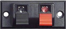
Typical spring-loaded connectors found on low to mid-range equipment.
Binding Post Terminals
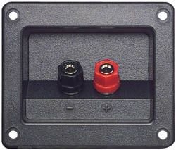
Normally used in pro or high power applications (over 150watts), binding posts create a connection by either accepting banana plugs, or by screwing down over spade connectors.
Binding posts make a significantly better connection to speaker wire than spring terminals do because the connections are more mechanically sound.
Speaker Wire
The wire that connects speakers to an amplifier. Usually a twin flexible wire with one "leg" identified by a stripe or a different colour so that the correct phase is maintained by connecting the Red speaker terminasl to the Red amplifier terminal etc
See also :Speaker wire gauge
SPL: Sound-Pressure Level.
Sound pressure is the local pressure deviation from the ambient (average, or equilibrium) pressure caused by a sound wave. Sound pressure can be measured using a microphone
The effective sound pressure is the root mean square of the instantaneous sound pressure over a given interval of time (or space) measured in dB. The human ear is a sound pressure sensitive detector. It does not have a flat spectral response, so the sound pressure is often frequency weighted such that the measured level will match the perceived level. When weighted in this way the measurement is referred to as a sound level. The International Electrotechnical Commission (IEC) has defined several weighting schemes. A-weighting attempts to match the response of the human ear to pure tones, while C-weighting is used to measure peak sound levels.If the (unweighted) SPL is desired, many instruments allow a "flat" or unweighted measurement to be made
Power Output of Loudspeakers
Loudspeakers are often rated at their electrical power maximum limits, which does not indicate the maximum acoustic output power available. A common definition of maximum acoustic output is when the distortion value has reached 10 % (20 dB). Thus the test method is similar to measuring loudspeaker distortion, except that the signal level is adjusted until the distortion is 10 %, and then the acoustic power level is measured with an SPL meter. This may be done at 997 Hz, or over a number of test frequencies spanning the audio range.
Surround Sound 5.1-channel, 6.1-channel, and 7.1-channel
Most home theatre systems utilize 5.1-channel surround sound consisting of three speakers (or channels) across the front (left, centre and right), two speakers in the back (left and right) and a subwoofer. The subwoofer is specifically for low frequency sounds like the "boomy" bass sounds from an explosion in an action scene or a bass drum in music. Since the subwoofer doesn't carry the full range of frequencies as the rest of the speakers/channels, it's considered the "1" in 5.1. 6.1-channel surround sound adds a centre-rear speaker to the 5.1 speaker arrangement. 7.1 adds two side speakers to the 5.1 arrangement. Dolby Digital and DTS are the prevalent audio formats for surround sound.
S-Video: (Super-Video)
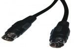
A video transmission standard that uses a 4 pin mini-DIN connector to send video information on two signal wires called luminance(brightness, Y) and chrominance(colour, C). S-Video is also referred to as Y/C. A composite signal, typically found coming out of an RCA jack on the back of most VCRs has the Y and C information combined into one signal. The advantage of having luminance and chrominance separated is that a comb filter is not needed inside the video projector to separate the composite signal into the luminance and chrominance signals. A comb-filter can reduce the sharpness of your video image.
SVGA: Super Video Graphics Array
SVGA is used to define a specific display resolution. Resolution is defined by the number of individual dots that a display uses to create an image. These dots are called pixels. An SVGA display has 800 horizontal pixels and 600 vertical pixels giving a total display resolution of 480,000 individual pixels that are used to compose the image delivered by a projector.
SXGA: Super eXtended Graphics Array
SXGA is used to define a specific display resolution. Resolution is defined by the number of individual dots that a display uses to create an image. These dots are called pixels. An SXGA display has 1280 horizontal pixels and 1024 vertical pixels giving a total display resolution of 1,310,720 individual pixels that are used to compose the image delivered by a projector.
UXGA: Ultra eXtended Graphics Array
UXGA is used to define a specific display resolution. Resolution is defined by the number of individual dots that a display uses to create an image. These dots are called pixels. A UXGA display has 1600 horizontal pixels and 1200 vertical pixels giving a total display resolution of 1,920,000 individual pixels that are used to compose the image delivered by a projector.
VGA: - Video Graphics Array
VGA is used to define a specific display resolution. Resolution is defined by the number of individual dots that a display uses to create an image. These dots are called pixels. A VGA display has 640 horizontal pixels and 480 vertical pixels giving a total display resolution of 307,200 individual pixels that are used to compose the image delivered by a projector.
WSXGA: Wide Super eXtended Graphics Array
WSXGA defines a class of SXGA displays with a width resolution sufficient to create an aspect ratio of 16:9. Resolution is defined by the number of individual dots that a display uses to create an image. These dots are called pixels. A WSXGA display has 1920 to 1600 horizontal pixels and 1080 to 900 vertical pixels respectively that are used to compose the image delivered by the projector.
WXGA: Wide eXtended Graphics Array
WXGA defines a class of XGA displays with a width resolution sufficient to create an aspect ratio of 16:9. Resolution is defined by the number of individual dots that a display uses to create an image. These dots are called pixels. A WXGA display has 1366 to 1280 horizontal pixels and 768 to 720 vertical pixels respectively that are used to compose the image delivered by the projector.
XGA: eXtended Graphics Array
XGA is used to define a specific display resolution. Resolution is defined by the number of individual dots that a display uses to create an image. These dots are called pixels. An XGA display has 1020 horizontal pixels and 768 vertical pixels giving a total display resolution of 783,360 individual pixels that are used to compose the image delivered by a projector.
TFT: Thin Film Transistor
A thin film transistor liquid crystal display (TFT-LCD) is a variant of liquid crystal display (LCD) which uses thin film transistor (TFT) technology to improve image quality (e.g. addressability, contrast). TFT LCD is one type of active matrix LCD, though all LCD-screens are based on TFT active matrix addressing. TFT LCDs are used in television sets, computer monitors, mobile phones and computers, handheld video game systems, personal digital assistants, navigation systems, projectors, etc.
UL: Underwriters Laboratory
Underwriters Laboratories Inc. (UL) is a U.S. privately owned and operated, independent, third party product safety testing and certification organization. Based in Northbrook, Illinois, UL develops standards and test procedures for products, materials, components, assemblies, tools and equipment, chiefly dealing with product safety.
USB (Universal Serial Bus)
USB ports are on virtually every PC and Mac made in the past 5 years (and on many that are older than that). A USB connection is often used to connect digital camcorders, digital cameras, mp3 players and other portable A/V devices as well as more recent products like digital media servers to a home theatre system. There are a few types of USB connectors. The USB Type A connector plugs into the USB port on your computer. The USB Type B connector plugs into a peripheral device (such as a monitor or printer). Compact devices like cameras and mp3 players typically have smaller USB jacks called a mini USB. All USB cables have a Type A connector on one end (for the computer) and either a Type B or mini USB connector on the other end.
VESA - Video Electronics Standards Association
VESA (Video Electronics Standards Association) is an international standards body for computer graphics founded in the late 1980s by NEC Home Electronics and eight other video display adapter manufacturers.
VESA's initial goal was to produce a standard for 800x600 SVGA resolution video displays. Since then VESA has issued a number of standards, mostly relating to the function of video peripherals in IBM PC compatible computers including dimensions for brackets used to fit monitors to walls, ceilings etc.
VGA Cables and Connectors
VGA cables are the common analogue LCD/DLP projector and monitor cables used today, though their life may be considerably shortened by the onset of digital technology with DVI and HDMI cables in the near future. See article VGA cables and connectors for projectors and monitors. A VGA connector as it is commonly known (other names include RGB connector, D-sub 15, mini sub D15 and mini D15) is a three-row 15 pin DE-15 connector (ie a D sub-miniature connector with E size case and 15 pins) See also: VGA connections for pin-outs and connector details etc or VGA Cables for AV Cable Kits for cable design considerations.
WiFi: Wireless Fidelity - IEEE 802.11
WiFi is based on the IEEE 802.11 specifications for wireless local area networks (WLAN) developed by a working group of the Institute of Electrical and Electronics Engineers (IEEE). There are four specifications in the family: 802.11, 802.11a, 802.11b, and 802.11g. All four use the Ethernet protocol and CSMA/CA (carrier sense multiple access with collision avoidance) for path sharing.
